The task of this controller application is to manage a LEGO® Mindstorms™ block sorter robot. In this context, the legOS custom firmware is used on the microcontroller to execute C written programs.
LEGO® Mindstorms™ Block Sorter Robot
This example shows how ANSI C code synthesis for MLDesigner FSM models is used to develop a controller application for a Hitachi H8 microcontroller.
The task of this controller application is to manage a LEGO® Mindstorms™ block sorter robot. In this context, the legOS custom firmware is used on the microcontroller to execute C written programs.
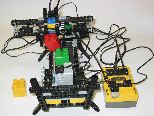
The block sorter robot represents a machine to sort different colored blocks in reference to their color lightness. Thereby, only two cases are considered: dark and bright colored blocks. While the machine is running, blocks are moving one after another on a conveyor belt until a sensor has been reached and activated by the first block. In reaction, the conveyor belt stops and color lightness of this block is determined. The measured value is compared to a threshold and, based on the result, a sorter unit unloads the block to either left or right side. Once the sorter unit is ready again, the conveyor belt moves on. Additionally, in case of interferences, a start/stop button is present to pause the procedure immediately and to continue it with a second press. In reference to this block sorter functionality, the underlying LEGO® robot includes two motor bricks to run the conveyor belt and to move the sorter unit. Furthermore, one touch sensor is used to activate the sorter unit at the end of the conveyor belt and a second one represents the start/stop button. Block color lightness is measured by a light sensor brick.


To use ANSI C code synthesis in conjunction with the controller application for the block sorter robot, the complete control function has to be developed on the basis of MLDesigner FSM models. Since the robot mainly consists of a conveyor belt and a sorter unit, the control function is decomposed into a conveyor belt controlling FSM and an automaton, which handles the sorter unit. To recompose the control function, a Conveyor Belt FSM instance and a Sorter FSM instance are interconnected inside a higher level controller FSM module. This FSM module also defines the input/output interface of the controller application.


After the function of the controller application has been developed in MLDesigner, the resulting controller FSM module can be validated on the basis of an appropriate system model.
Inside this system, an additional mission level environment model is interconnected with a controller FSM module instance. During simulation, this environment model is mainly used to produce significant signals for the controller FSM module and to evaluate and display corresponding outputs. In other words, it simulates actuators and sensors of the real block sorter robot.
The main environment components are thereby an interactive control panel with two buttons and a 3D visualization of the robot. One control panel button is used to put a new random colored block on the conveyor belt of the 3D block sorter model and the second button represents the real start/stop button.
Based on control panel activities, the 3D block sorter model visualizes all controller FSM module outputs and produces relevant sensor events, for instance, when a block reached the touch sensor or the light sensor is active.
Such a qualified and realistic simulation model enables detailed testing of the controller FSM module functions.
To produce functional equivalent C code, the controller FSM module is used as input model for the ANSI C code generator. In this context, name and path of the target directory for the output source files have to be determined by the configuration dialog. Furthermore, a minimum integer size of 8 bit can be selected, because integer values within the controller application will not exceed the corresponding range limit. After the configuration dialog has been accepted by the Generate button, the code generator produces the ANSI C implementation of the controller FSM module and creates all related source files inside the selected directory.
Before the generated code can be downloaded and executed on the microcontroller, it has to be customized and compiled on a host computer, which provides the legOS API and C compiler.
In this context, the CFG_Base.h configuration file can be left unmodified for several reasons.
The RTOS clock tick configuration within the CFG_OS.c file can be limited to modifications of the ctWaitNextTick function, since the Hitachi H8 microcontroller is not a real-time system. In doing so, this method is implemented in such a way that after all tasks for the present system time have been processed, the RTOS scheduler gives up control to legOS for 100ms. Afterwards, the clock tick handler is called.
To setup the controller application input/output interface, all input get as well as output send functions of the CFG_IO.c file have to be configured using motor and sensor driver functions. These functions are provided by the legOS API. Additionally, three local boolean variables are used in connection with sensor activities and motor speeds are initialized by the ioSetup function. As a result of legOS is not strictly ANSI C conform and does not support standard input/output streams, the corresponding include statement has to be removed from the Types.h source file to satisfy the legOS C Compiler. Except this minor modification, all other non-configuration files can be left untouched.
Here are the customized configuration files of the block sorter controller application.
#ifndef __CFG_Base_h
#define __CFG_Base_h

typedef char int8bit;
typedef unsigned char uint8bit;

typedef short int int16bit;
typedef unsigned short int uint16bit;

typedef long int int32bit;
typedef unsigned long int uint32bit;

typedef unsigned char IntegerT;
typedef double FloatT;

/* maximum number of allowed clock ticks between
the scheduled time stamp of an event and its real
dispatching point in time */
#define REAL_TIME_LEVEL 0

/* number of blocks in the IntegerT memory partition */
#define MEM_NUM_IntegerT_BLOCKS 6

/* number of blocks in the event queue memory partition */
#define MEM_NUM_EVENT_QUEUE_ENTRIES 6
#define SEED 123456789
#define USE_RANDOM_SEED 0

/* debug FSM "ConveyorBelt" */
#define FSM0_DEBUG 0

/* debug FSM "Sorter" */
#define FSM1_DEBUG 0

/* debug runtime errors */
#define DEBUG_RUNTIME_ERRORS 0

/* debug task execution */
#define OS_DEBUG_TASK 0

/* debug task input data */
#define OS_DEBUG_DELIVER_DATA 0

/* debug task output data */
#define OS_DEBUG_EMIT_DATA 0

/* debug interface input data */
#define IO_DEBUG_INPUT_DATA 0

/* debug interface output data */
#define IO_DEBUG_OUTPUT_DATA 0

/* debug dynamic memory allocation and de-allocation */
#define MEM_DEBUG 0

#endif
#include <unistd.h>
#include "Types.h"

/* external clock tick counter declaration */
extern uint32bit ct_Counter;

/* external os abort flag declaration */
extern BooleanT os_Abort;

/* external clock tick handler declaration */
void ctHandler(void);

/* external error function declaration */
void osErrorAbortRun(const StringT* pMessage);

void
ctSetup(void)
{
}

void
ctWrapup(void)
{
}

void
ctWaitNextTick(void)
{
  msleep(100);
  ctHandler();
}

void
ctOverrunHandler(void)
{
}

void
ctCounterOverflowHandler(void)
{
}

void
tmrTimeStampOverflowHandler(void)
{
}

void
userSetup(void)
{
}

void userWrapup(void)
{
}
#include <dmotor.h>
#include <dsensor.h>
#include <rom/lcd.h>
#include <conio.h>

#include "IO_Ports.h"
#include "Types.h"

/* external error function declaration */
void osErrorAbortRun(const StringT* pMessage);

static BooleanT io_ButtonOnOff_Pressed = 0;
static BooleanT io_TouchSensor_Pressed = 0;
static BooleanT io_LightSensorActive = 0;

/* ==== USER I / O CONFIGURATION FUNCTIONS ==== */
void
ioSetup(void)
{
  motor_a_speed(100);
  motor_c_speed(100);
}

void
ioWrapup(void)
{
}

void
ioUserGetInputs(void)
{
}

/* ==== USER INPUT INTERFACE FUNCTIONS ======== */
static BooleanT
get_ButtonOnOff(IntegerT* pData)
{
  if (TOUCH_1)
  {
    if (io_ButtonOnOff_Pressed == 0)
    {
      io_ButtonOnOff_Pressed = 1;
      return 1;
    }
  }
  else
    io_ButtonOnOff_Pressed = 0;

  return 0;
}

static BooleanT
get_LightSensor(IntegerT* pData)
{
  int tLight;
  if (io_LightSensorActive)
  {
    tLight = LIGHT_2;
    *pData = tLight;
    cls();
    lcd_int(tLight);
    return 1;
  }
  return 0;
}

static BooleanT
get_TouchSensor(IntegerT* pData)
{
  if (TOUCH_3)
  {
    if (io_TouchSensor_Pressed == 0)
    {
      io_TouchSensor_Pressed = 1;
      return 1;
    }
  }
  else
    io_TouchSensor_Pressed = 0;

  return 0;
}

/* ===== USER OUTPUT INTERFACE FUNCTIONS ====== */
static void
send_BandOn(IntegerT pData)
{
  motor_a_dir(fwd);
}

static void
send_BandOff(IntegerT pData)
{
  motor_a_dir(brake);
}

static void
send_SorterMotor(const EnumT* pData)
{
  if (pData->mIndex == 0)
    motor_c_dir(brake);
  else if (pData->mIndex == 1)
    motor_c_dir(fwd);
  else
    motor_c_dir(rev);
}

static void
send_LightSensorOn(IntegerT pData)
{
  io_LightSensorActive = 1;
  ds_active(&SENSOR_2);
}

static void
send_LightSensorOff(IntegerT pData)
{
  io_LightSensorActive = 0;
  ds_passive(&SENSOR_2);
}