Switch to Simulation Mode
The Switch to Simulation Mode icon is visible on the toolbar when a System is opened in the Model Editor window. Click the icon to switch to simulation mode. The simulation run control icons are now visible on the toolbar.
![]()
The Switch to Simulation Mode icon is visible on the toolbar when a System is opened in the Model Editor window. Click the icon to switch to simulation mode. The simulation run control icons are now visible on the toolbar.
![]()
The run controls apply to the system that was active when you clicked the Simulate icon. If you want to run another system without physically closing the active system, first click the Switch to Edit Mode icon before selecting a new system to simulate.
To start the simulation click this icon. Notice the Progress tab at the bottom of the GUI showing the progress of the simulation.
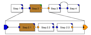
The simulation is advanced to the next block. If the next block in the system is a hierarchical module, the first block within the module is highlighted. The firing order is Step 1, Step 2.1, Step 2.2, Step 2.3, Step3, Step 4.
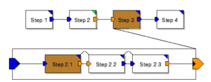
The simulation is advanced to the next block on the same hierarchical level in the system. The firing order is Step 1, Step 2, Step 3, Step 4. Clicking Step Over when Step 2 is highlighted causes Step 2.1, Step 2.2 and Step 2.3 to execute and the simulation pauses at Step 3.
![]()
If the simulation has advanced to an instance within a module it is possible to execute all events in the module and advance to the next model instance outside the module. Clicking Finish while Step 2.1 of the hierarchical model Step 2 is highlighted advances the simulation to Step 3. Clicking Finish while step 3 is highlighted causes the simulation to run through to the end.
Calls the wrap-up command and all graphs are produced if enough information was available for the end conditions to be met.
The simulation is halted and reset.
Model instances and ports are highlighted as they fire during the simulation. This slows the simulation down a lot but is useful in connection with Breakpoints for debugging systems.
The formal ports of the modules are not highlighted because they do not exist in kernel during simulation. A system containing no wormholes is, after compilation, nothing else than a plain network of primitive instances.
Opens the Animation console. A textual report of each port firing or model instance firing is printed to the Animation console. This is useful for checking firing order of model elements and wormholes.
Activates/deactivates all breakpoints in the active system.
Opens the FSM States console. The FSM States console lists the FSMs used in the current system along with their Current State.
A single click on the icon generates code to run the simulation externally using the method chosen in the Settings configuration of the main menu.
The default method. The files are created in the target directory but are not compiled.
A PTcl file (.ptcl) is generated at a location of your choice.
A single click on the icon generates code and runs the simulation externally using the method chosen in the Settings configuration of the main menu.
Generates all object files needed to run a simulation externally (independent of the MLDesigner GUI), compiles and executes the simulation once. All files are written to $MLD_USER/SYSTEMS/Library Name/System Name unless otherwise specified in the Target Directory property of the Simulation Properties window.
At a location of your choice a PTcl file (.ptcl) is generated and executed.
Opens a graph file of your choice (.pxgo) either in a Text Editor or an X Graph.