Creating an FSM
For a better understanding of this page you should know how to:
A commonly used example for control-intensive software environments is the so-called "reflex game".
The "reflex game" can be found at MLD Libraries→FSM Domain→Demos FSM→Reflex Game2. In this example we demonstrate how to create the FSM instance game2_FSM#1 used in the Demo. We then instantiate the FSM in a copy of this system (saved in your user library) and reference slave processes. These are the fundamental principles of the FSM domain and following the example here will demonstrate the MLDesigner FSM interface simply and effectively.
System Description
This version of the reflex game has two players. Each player has two buttons to press during the game: player one has coin and go and player two has ready and stop. The normal gameplay should proceed as follows:
- Player1 presses coin to begin. The status light turns blue.
- When Player2 presses ready the status light turns yellow.
- Player1 presses go to start the game. When the status light turns green Player2 has to press stop as fast as possible.
- The game ends after Player2 presses stop. The status light turns red. The time between Player 1 pressing go and Player2 pressing stop is indicated in the Time elapsed display of the game control console.
The game times out, indicated by the light display area of the Tcl display becoming light grey, if:
- Player2 does not press ready within a certain time from the moment Player1 pressed coin.
- Player2 presses stop before or exactly when Player1 presses go.
- After Player1 presses go, Player2 does not press stop within a certain amount of time.
Another additional rule is that if Player1 does not press go within an amount of time after Player2 presses ready, then go will be asserted by the system and the game advances to the next step and Player2 is expected to press stop.
Example
The reflex game is a mixture of FSMs, some DE modules, one SDF module and some Tcl scripts.
The Tcl scripts and the implementation of the DE and SDF domains are not discussed extensively in this chapter. For more information on combining models refer to the Modeling Guide. This chapter only implements the FSMs and the interface of each FSM to the other modules.
The ReflexGame2 is the topmost system. The reflex game is a realtime game and is therefore modeled in the DE domain. A brief explanation of the system is:
- Clock generates a sequence of clock ticks which are synchronized by Synchronize.
- Player1, Player2 and Display are Tcl scripts to create the buttons and output lights.
- Game2_FSM#1 models the main behavior of the game, it consists of two states.
ReflexGame2 System in the
DE domain
To create the game FSM proceed as follows:
- Create a new Library called MyFSM.
- Create a new FSM below MyFSM and name it MyReflex.
The new FSM module is now open in the Model Editor Window and has a Memory model instance called CurrentState. In this context, the Current State Memory can not be deleted from the FSM model. The type of this Memory argument is always set to the associated Current State Data Structure. During execution, the value of the Current State Memory is always the logical name of the current state of the finite state machine. If the scope of this Memory argument is external, another block linked to this Memory argument can change the finite state machine’s current state.
Changing the value of the Current State Memory from outside the FSM block or via an FSM Action statement causes no action execution.
The state, specified by the value of the Current State Memory, becomes the current state. If this state is a hierarchical state, its default entrance destination becomes the current state and so on; until the destination of a default entrance is a leaf state.
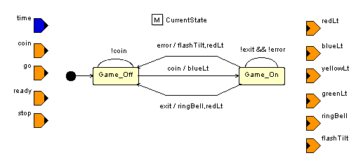
We now need to create the two states called Game_On and Game_Off.
- Click the
 icon and place the cursor inside the Model Editor Window.
- Click the mouse twice to create two states with the default names State0 and State1. A right-click returns the cursor to selection mode.
- Arrange the states so you can see both clearly.
- Select one state instance to activate the State Properties plane in the Property Editor window and change the Logical Name to Game_on. Repeat this step with the second state instance and call it Game_Off.
It is not possible to define expressions for transitions before you have created events and attempting to do so will result in an Invalid Event Expression warning being displayed. Events are generated by input ports, event arguments, or by internal events. Internal events are set by Slave Processes and are not connected to the interface of this FSM module. The first step here is to create the input/output ports and then the internal events. Proceed as follows:
- Select the
 icon on the toolbar and click five times with the cursor placed over the left edge of the bounding box. Move the cursor slightly after each click to space the input ports evenly.
- Repeat the previous step but select the
 icon and click six times over the right edge of the bounding box.
 The ports are all named Input1 to Input5 and Output1 to Output6. We need to rename the ports so it is easy to identify which port is which when we instantiate the FSM module into the system, and to define the event names for the transition expressions. Rename the ports in the Port Properties window according to the figure beside. Here the port name is the event identifier. At the same time change the Data Type of the ports to int except for the time input port which has type float.
- Click on the model background to activate the FSM Properties window.
- In the Internal Events property type exit error to define the two events.
- Now the FSM model needs a Default Entrance. Click the
 icon on the toolbar to change the cursor mode. Click once in the Model Editor Window to place the default entrance (a black dot) close to the Game_Off instance. A right-click returns the cursor to selection mode. You do not need to set any action for the default entrance but you do need to define which state is the starting point of the FSM module. Draw a transition from the default entrance to the Game_Off state to define the starting point.
The next step is to create the transitions needed for the FSM to function.
- Select the
 icon on the toolbar and move the cursor over the Game_On state.
- Click once to see the Self Transition appear as a loop back to itself. Another click anchors the transition on the state.
- Repeat the previous step with the Game_Off state.
- Click on the Game_On state once and move the cursor towards the Game_Off state. Click the mouse once to complete the transition. Repeat the procedure from Game_On to Game_Off but first move the cursor slightly up and click the mouse once on the model background to create a node anchor so that the two transitions do not overlap. Now perform the same procedure in the opposite direction to create a transition from Game_Off to Game_On.
The transition is directional so the direction the connections are made in plays an important role.
Return the cursor to selection mode with a right-click. The transitions may need to be arranged so they look neat and do not overlap one another. There are sliding nodes on the transitions that are visible as soon as you move the cursor over an edge of a transition. Arrange the transitions to look something like those in the figure above.
The next step is to define the Conditions and Actions for each transition.
- Select the transition going from Game_Off to Game_On.
- In the Event Expression input field type coin.
- In the Action input field type WriteOutput(blueLt,1);.
- Change the Entry Type in the Transition properties window from History to Default.
- Select one of the transitions going from Game_On to Game_Off.
- In the Event Expression input field type error.
- In the Action input field type WriteOutput(flashTilt,1); WriteOutput(redLt,1);.
- Select the other transitions going from Game_On to Game_Off.
- In the Event Expression input field type exit.
- In the Action input field type WriteOutput(ringBell,1); WriteOutput(redLt,1);.
- Select the self transition of the Game_Off state. In the Event Expression input field type !coin. The same is entered in the Label input field automatically.
- Select the self transition of the Game_On state. In the Event Expression input field type !exit && !error. The same is entered in the Label input field automatically.
- Save the model.
The next step would be to create the slave processes which are needed for this system to run. For this exercise, however, we will merely show how the slave processes are referenced by the top level FSM. When the system is running with your FSM you can look at all the instances and analyze how the slave processes work. It makes sense to read the rest of this chapter while going through the system.
The simplest way to get this system running is to open the Demo system MLD Libraries→FSM Domain→Demos FSM→Reflex Game2→ReflexGame2 and select Save As from the main File menu. Save the system in your MyFSM library. With the newly saved system open in the Model Editor Window, select the MyReflex FSM in the Tree View and drag it over the Game2_FSM#1 instance. You will see the color of the model instance change indicating it is possible to replace the instance with your FSM. Release the mouse button to replace the model instance while keeping all connections between ports intact. If all port names were typed correctly as per the example, all connections will be replaced as well. If any connections are not intact, check your FSM port names and make sure they are the same as the demo FSM.
The Slave Process must now be defined:
- Double-click the MyReflex model instance.
- Select the state Game_On to activate the State Properties window.
- Click on the field Slave Path and click the Module icon to open the Select Slave Model dialog.
- Select MLD Libraries→FSM Domain→Demos FSM→Reflex Game2→GameOn as the slave process and click OK.
- Save the model.
The game can now be started using your FSM and the GameOn slave process.
At the moment, MLDesigner is not able to determine internal events. Always check that the field is properly set (to use the events) and that these events are properly controlled by slave processes.
The GameOn module is a slave process consisting of the rules for the two players. This module is implemented in the DE domain and is nothing more than a divert to two other FSMs that implement two rules of the game.
If we analyze the GameOn module, we can see how the interfaces to FSMs are implemented. Once again, the events to be controlled are implemented as input and output ports (the names of these ports are, of course, identical to the events in the master FSM). The DE module consists of two concurrent FSMs to implement the rules of the game. These are interconnected using a zero-delay(!) loop and thus form an instantaneous dialog between the two players.
The two slave FSMs are created in exactly the same way as the MyReflex FSM explained above. They can be found at MLD Libraries→FSM Domain→Demos FSM→Reflex Game2→rule1_FSM and MLD Libraries→FSM Domain→Demos FSM→Reflex Game2→rule2_FSM.
The GameOn slave module containing rule1_FSM and rule2_FSM
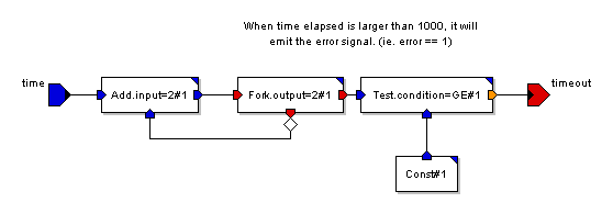
In several states, we need to count ticks from the clock (each clock is given as an event, in our system simply called time, and has been given to every slave process). The counting is a simple arithmetic computation that can be performed using the dataflow graph. This graph, realized in the SDF domain, simply counts ticks, compares the count against a constant (this denotes the maximum time) and emits a timeout event when the threshold is exceeded.
The count module, in
SDF domain