Create or open a model
To construct a new model you must first create the model components.
The first step is to create a library to group all the components. You will then create the system and module components.
Create Sine Modulator Library
- Right-click on My Libraries and choose New Model→Library to open the Create New Model dialog.
- Enter the Logical Name as Sine Modulator Library.
- Press the tab key to change the input focus, which causes the Physical Name to be filled in automatically.
- Leave the Library as it is.
- Type This library contains a sine modulator as Description.
- Click the OK button.
Now, you should have a new library with the name Sine Modulator Library as a subentry of the My Libraries entry.
Create Sine Modulator System
- Right-click on the newly created Sine Modulator Library and choose New Model→System to open the Create New Model dialog.
- Enter the Logical Name as Sine Modulator System.
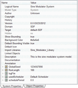
- Click in the Description field and enter This is the sine modulator system model. You will notice that due to the change of input focus Physical Name was filled in automatically.
- Leave the Library as it is, it should already read Sine Modulator Library.
- Select SDF from the Modeling Domain drop-down menu.
- Click the OK button.
Now, you should see the new system with the name Sine Modulator System as a subentry of the previously created Sine Modulator Library. Also, you should notice that the newly created system was automatically opened in the Model Editor.
Create Sine Modulator and Sine Generator
- Right-click on the Sine Modulator Library and choose New Model→Module to open the Create New Model dialog.
- Enter the Logical Name as Sine Modulator.
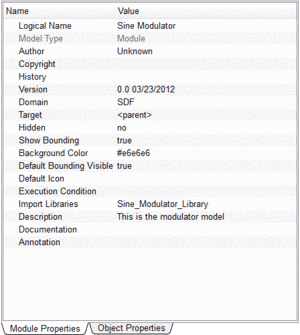
- Enter This is the modulator model as Description.
- Click the OK button.
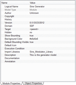
- Add another Module with the Logical Name Sine Generator and the Description This is the generator model.
Now, you have created the model components including the library needed for this example. Like it happened when you created the system, two additional Model Editor windows should have appeared containing the Sine Modulator and Sine Generator, respectively.
The models created for our example have predefined properties according to the values we specified in the Create New Model dialog. Switch to the relevant Model Editor Window to view the parameters in the Property Editor for these models.
 |
 |
 |
| (a) Sine modulator system |
(b) Sine modulator module |
(c) Sine generator module |
The next step is to add input and output ports.