Sine modulator example
This example takes you through the steps required to create a complete model.
The first step is to create a library to group all the components. You will then create the system and module components.
Create Sine Modulator Library
- Right-click on My Libraries and choose New Model→Library to open the Create New Model dialog.
- Enter the Logical Name as Sine Modulator Library.
- Press the tab key to change the input focus, which causes the Physical Name to be filled in automatically.
- Leave the Library as it is.
- Type This library contains a sine modulator as Description.
- Click the OK button.
Now, you should have a new library with the name Sine Modulator Library as a subentry of the My Libraries entry.
Create Sine Modulator System
- Right-click on the newly created Sine Modulator Library and choose New Model→System to open the Create New Model dialog.
- Enter the Logical Name as Sine Modulator System.
- Click in the Description field and enter This is the sine modulator system model. You will notice that due to the change of input focus Physical Name was filled in automatically.
- Leave the Library as it is, it should already read Sine Modulator Library.
- Select SDF from the Modeling Domain drop-down menu.
- Click the OK button.
Now, you should see the new system with the name Sine Modulator System as a subentry of the previously created Sine Modulator Library. Also, you should notice that the newly created system was automatically opened in the Model Editor.
Create Sine Modulator and Sine Generator
- Right-click on the Sine Modulator Library and choose New Model→Module to open the Create New Model dialog.
- Enter the Logical Name as Sine Modulator.
- Enter This is the modulator model as Description.
- Click the OK button.
- Add another Module with the Logical Name Sine Generator and the Description This is the generator model.
Now, you have created the model components including the library needed for this example. Like it happened when you created the system, two additional Model Editor windows should have appeared containing the Sine Modulator and Sine Generator, respectively.
The next step in this example is to create ports for Sine Modulator and the Sine Generator modules. Ports cannot be defined in the system model Sine Modulator System.
Add output to Sine Generator
- Select the Model Editor Window containing the Sine Generator module.
- Use the Add Output Port tool button to switch to port creation mode.
- Click on model background at the position where the port will be created.
- Click the right mouse button to switch back to normal selection mode.
- Select the created port. MLDesigner will show port properties in the property editor.
- Set the port name to Output.
- Select the data type float.
- Set the description to The sine signal output.
- Save the model using the tool button Save Model (Ignore construction error messages).
Add input and output to Sine Modulator
- Select the Model Editor Window that contains the Sine Modulator module.
- Use the Add Input Port tool button to switch to port creation mode.
- Click on model background at the position where the port will be created.
- Click the right mouse button to switch back to normal selection mode.
- Select the created port. MLDesigner will show port properties in the property editor.
- Set the port name to Input.
- Select the data type float.
- Set the description to The input signal.
- Remain in the Model Editor Window containing the Sine Modulator module.
- Use the Add Output Port tool button to switch to port creation mode.
- Click on model background at the position where the port will be created.
- Click the right mouse button to switch back to normal selection mode.
- Select the created port. MLDesigner will show port properties in the property editor.
- Set the port name to Output.
- Select the data type float.
- Set the description to The output signal.
- Save the model using the tool button Save Model (Ignore construction error messages).
The next step in this example is the creation of parameters Frequency and SampleRate for our Sine Generator module. Switch to the Model Editor Window that contains the Sine Generator module and follow the steps below. Exporting parameters will be demonstrated for the creation of the parameters of the Sine Modulator module in Set parameters of model instances.
Add parameter Frequency to Sine Generator
- Select the Model Editor Window that contains the Sine Generator module.
- Right-click in the property editor and select the item New Parameter.
- Expand Parameter1 if necessary.
- Set the name to Frequency.
- Set the type to float.
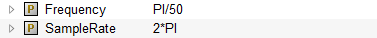
- Set the default value to PI/50.
- Set the description to The frequency of the generated sine wave.
- Collapse the changed parameter Frequency.
Add parameter SampleRate to Sine Generator
- Right-click in the property editor and select the item New Parameter.
- Set the name to SampleRate.
- Set the type to float.
- Set the default value to 2*PI.
- Set the description to The sample rate of the module.
- Save the model using the tool button Save Model (Ignore error message).
The next step is to include the model instances for the model components we need for the sine modulator example. Follow the steps below to add the instances for the Sine Generator, Sine Modulator, and Sine Modulator System.
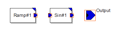
Add model instances to Sine Generator
- Open the Sine Generator module.
- Expand the library MLD Libraries→SDF Domain→Sources.
- Drag the item Ramp into the Model Editor Window.
- Expand the library MLD Libraries→SDF Domain→Nonlinear.
- Drag the item Sin into the Model Editor Window.
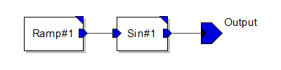
- Arrange the components in the Model Editor Window as shown below.
- Save the model using the tool button Save Model.
Ignore the construction errors. The error is displayed because there is no output/input port for the module and/or the ports are not connected or terminated.
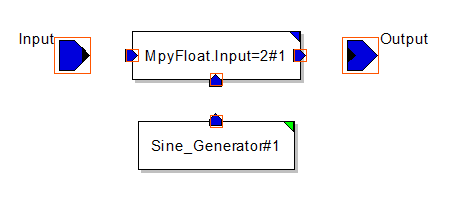
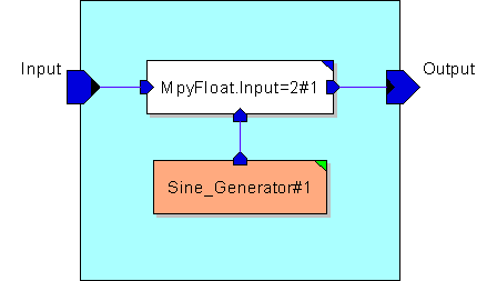
Add model instances to Sine Modulator
- Open the Sine Modulator module.
- Expand the library MLD Libraries→SDF Domain→Arithmetic.
- Drag the item MpyFloat into the Model Editor Window.
- From the Select Special Primitive dialog select MpyFloat.Input=2.
- Expand your library Sine Modulator Library.
- Drag item Sine Generator into the Model Editor Window.
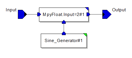
- Arrange the components as shown below and Save the model (Ignore construction error messages).
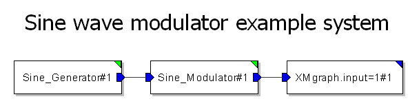
Add model instances to Sine Modulator System
- Open the Sine Modulator System.
- Expand the library MLD Libraries→SDF Domain→Sinks.
- Drag the item XMGraph.Input=1 into the Model Editor Window.
- Expand your library Sine Modulator Library.
- Drag the items Sine Generator and Sine Modulator into the Model Editor Window.
- Arrange the components as shown below and Save the model (Ignore construction error messages).
To demonstrate parameter setting and linking mechanisms, let us set the model instance parameter values of our example. Different methods for achieving the same result are demonstrated here such as linking and export.
Set an actual parameter of the Ramp instance
First, you must set the actual parameters of the Ramp instance in the Sine Generator module.
- Select the Model Editor Window containing the Sine Generator module.
- Click on the Ramp model instance.
- Click on the value field of the parameter step.
- Set the value to 2*PI*$Frequency/$SampleRate.
- Save the model using the tool button Save Model (Ignore the construction errors).
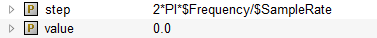
You have now set the actual parameter step of the Ramp instance to an expression that contains the formal model parameter names. This realizes indirect linking between the Ramp parameter and the Sine Generator parameter.
 |
 |
| (a) Sine Generator module properties |
(b) Ramp instance properties |
Export actual parameters of the Sine Generator instance
The next step is to set the actual parameter of the Sine Generator instance in the Sine Modulator model. The Sine Generator has two actual parameters Frequency and SampleRate. Since the sample rate should be constant in the whole system model hierarchy it should be settable on the system model level. The Frequency of the sine modulator should be a parameter on the system model level. Therefore, it is necessary to export the SampleRate and Frequency parameters to the next higher model level. Follow the steps below to export these two parameters.
- Select the Model Editor Window that contains the Sine Modulator module.
- Click on the Sine Generator model instance in the Model Editor Window.
- Right-click on the parameter Frequency, and click Export.
- Right-click on the parameter SampleRate, and click Export.
- Save the model using the tool button Save Model (Ignore the construction error messages).
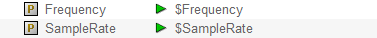
The green arrows in both fields indicate that these parameters are successfully exported.
By exporting the actual parameters Frequency and SampleRate of the Sine Generator instance, you have automatically created the two formal model parameters of the Sine Modulator module.
 |
 |
| (a) Sine Modulator module properties |
(b) Sine Generator instance properties |
Create system model parameters
The last step is to create the system model parameters. You need two different frequencies; one for the signal frequency, and a carrier frequency for the sine modulator as well as a system model parameter for the sample rate.
Export actual parameters of the second Sine Generator instance
- Select the Model Editor Window that contains the Sine Modulator System model.
- Click on the Sine Generator model instance.
- Right-click on the parameter Frequency, and click Export As.
- Set the name of exported parameter to SignalFrequency and click OK.
- Right-click on the parameter SampleRate, and click Export.
Export and link actual parameters of the Sine Modulator instance
- Click on the Sine Modulator model instance.
- Right-click on the parameter Frequency, and click Export As.
- Set the name of exported parameter to CarrierFrequency and click OK.
- Right-click on the parameter SampleRate, point to Link to, and click on SampleRate.
Set Sine Modulator System parameters
- Click on the Sine Modulator System model background.
- Click on the value field of the parameter SignalFrequency and enter the value PI/100
- Click on the value field of the parameter CarrierFrequency and enter the value 0.2*PI.
- Save the model using the tool button Save Model, ignore the construction error messages.
You have created the system parameters SignalFrequency, CarrierFrequency, and SampleRate by exporting the model instance parameter. However, the setting of the actual parameter SampleRate of the Sine Modulator model instance was realized by linking the parameter to the existing system model parameter SampleRate. Now you can control the whole model using system parameters. By setting their Scope to External in the System Properties window, you can control them directly in the Simulation Properties window (see Simulation with MLDesigner).
The next step is to connect the model instances of the example models. Start with the creation of connections in the Sine Modulator model.
- Select the Model Editor Window that contains the Sine Modulator model.
- Double-click on the Output port of the Sine Generator instance to start a new connection.
- Click on Input#2 port of the MpyFloat.Input=2 instance to complete the connection.
- Double-click on the Input port of the module to start a new connection.
- Click on Input#1 port of the MpyFloat.Input=2 instance to complete the connection.
- Double-click on the Output port of the MpyFloat.Input=2 instance to start a new connection.
- Click on the Output port of the module to complete the connection.
- Save the model using the tool button Save Model.
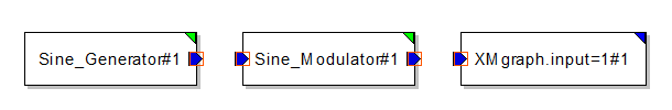
Repeat these steps for the Sine Generator and Sine Modulator System. Your models should now look like this.
 |
 |
| (a) Sine Generator module |
(b) Sine Modulator module |
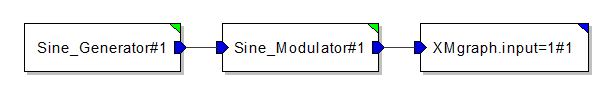 |
| (c) Sine Generator System model |
Unused ports must be terminated. This is achieved by choosing Terminate from the context menu while the relevant port is selected. In these cases the appropriate BlackHole primitive for output ports and the Const or NULL primitive for input ports for the domain are instantiated.
The next step is to add a descriptive label to the Sine Modulator System.
- Select the Model Editor Window that contains the Sine Modulator System model.
- Click the Add Text Label toolbar button to switch to label creation mode.
- Click on the model background where you want the label to be.
- Right-click to leave label creation mode.
- Select the label and enter Sine wave modulator example system as Text in the Label Properties.
- Choose a Font for the label and increase the size of the font.
- Reposition the label if you have to and Save the model.
The next step is to color the previously created model components.
- Select the Model Editor Window that contains the Sine Generator model.
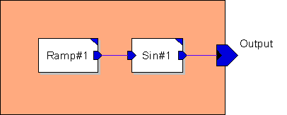
- Click on the model background and set the Background Color in the Module Properties to #ffaa7f.
- Save the model.
- Select the Model Editor Window that contains the Sine Modulator model.
- Click on the model background and set the Background Color in the Module Properties to #aaffff.
- Select the Sine Generator instance and set the Color in the Instance Properties to #ffaa7f.
- Save the model.
- Select the Model Editor Window that contains the Sine Modulator System model.
- Select the Sine Generator instance and set the Color in the Instance Properties to #ffaa7f.
- Select the Sine Modulator instance and set the Color in the Instance Properties to #aaffff.
- Save the model.
 |
 |
| (a) Sine Generator module |
(b) Sine Modulator module |
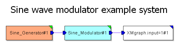 |
| (c) Sine Generator System model |
Follow the steps below to make SignalFrequency and CarrierFrequency visible within the Simulation Properties window.
- Select the Model Editor Window that contains the Sine Modulator System model.
- Click on the Sine Modulator System model background to activate the System Properties plane in the Property Editor.
- Set the Scope of SignalFrequency to External.
- Set the Scope of CarrierFrequency to External.
- Save the model using the tool button Save Model.
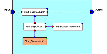
To demonstrate the using of Tk primitive modules we will modify the Sine Modulator model. Follow the steps below to modify the Sine Modulator module as shown in the figure.
- Select the Model Editor window that contains the Sine Modulator module.
- Expand the Tree View to MLD Libraries→SDF Domain→Tcl/TK.
- Drag item TkBarGraph into the Model Editor window. From the Select Special Primitive dialog select TkBarGraph.input=1
- Expand the library MLD Libraries→SDF Domain→Control.
- Drag item Fork into the Model Editor window. From the Select Special Primitive dialog select Fork.output=2
- Connect the model instances as the figure indicates.
- Click on the TkBarGraph.input=2 model instance.
- Click on the value field of the parameter number_of_bars.
- Set the value to 32.
- Save the model using the toolbar button Save Model.