Code Customization
An accurate and efficient execution of a generated FSM module application on a specific run-time system is affected by several hardware/software architecture layers.
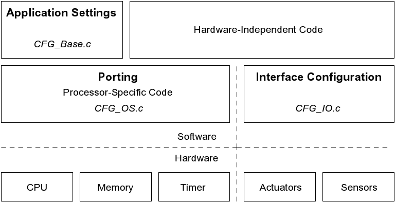
Analogous to the three existing configuration files, the output code customization is divided into three functional parts. The figure below shows the different customization layers within a hardware/software architecture.
Hardware/Software Architecture - Customization Layers
General Settings
Global and universal valid settings are handled separately by the CFG_Base.h configuration file. First of all, this customization unit includes a section for data type related settings. Especially important is the range and byte size definition of numeric integer and floating point data types. These settings are highly run-time system dependent.
Additionally, if an input model uses numeric vectors or strings, an appropriate maximum number of elements can be determined within this data type configuration section.
The real-time level of the application can be defined by the maximum number of allowed clock ticks between the scheduled timestamp of an event and its real dispatching point in time. In case of hard real-time conditions, the real-time level has to be set to 0.
For all existing custom memory partitions an optimized number of reserved partition blocks can be set.
In conjunction with random number generator built-in functions, a constant global seed is definable or a random seed can be enabled. Latter one is based on the run-time system clock. Finally, a set of boolean switches is present to enable miscellaneous debug code sections.
Porting
MLDesigner FSM code synthesis produces highly portable and strictly ANSI C conform code without any run-time system dependencies. In doing so, some processor specific code in C and/or assemply language is necessary to adapt a particular RTOS to a microprocessor or microcontroller. Clock tick handling is thereby the most critical configuration part for several reasons.
- Dependent on appropriate real-time conditions, an accurate clock tick interval has to be determined. This usually requires a certain trade-off, because a short CTI provides in fact exact timing, but on the other hand, the microprocessor must execute a clock tick handling routine frequently. Therefore, a short clock tick can decrease system throughput quite considerably by increasing the amount of microprocessor time spent in the clock tick handling routine.
- The setup has to ensure an independent and cyclical clock tick occurrence. In this context, an interrupt service routine or a periodic timer signal approach has to be used to call a clock tick handling routine.
- A code synthesis RTOS has to be configured in such a way that CPU is not permanently blocked by the scheduler, while it is waiting for the next clock tick. Especially in case of a generated application is used as a single task of a superordinate multitasking operating system, it has frequently to give up CPU control, when no more FSM instances have to be performed for current system time. Otherwise, the multitasking operating system is not able to perform concurrent tasks.
- The real-time violation handler has to be configured according to either soft or hard real-time conditions.
Since the clock tick counter is represented by an unsigned integer variable of a finite range, a CTC overflow occurs when the counter exceeds range limit and is instead set back to zero. In case of such an integer range overflow is critical in a specific application area, the RTOS configuration file CFG_OS.c includes a CTC overflow handler function.
The following table lists all template functions of the CFG_OS.c configuration file.
RTOS Porting Functions
|
Template Function
|
Desciption
|
|
ctSetup
|
used for clock tick setup, e.g., to start a timer ISR
|
|
ctWrapup
|
used for clock tick wrap-up, e.g., to stop a timer ISR
|
|
ctWaitNextTick
|
called whenever scheduler waits for next clock tick, e.g., to give up CPU control
|
|
ctCounterOverflowHandler
|
CTC overflow handler
|
|
osRealTimeViolationHandler
|
real-time violation handler
|
|
userSetup
|
additional user setup, called before ctSetup
|
|
userWrapup
|
additional user wrap-up, called before ctWrapup
|
Interface Configuration
The interface configuration file CFG_IO.c is used to define a hardware/software inteface for a generated FSM module application within an embedded real-time system. In other words, to connect original FSM module input/output interface ports with appropriate actuator and sensor hardware components. Therefore, the customizable generic get and send functions, used by the RTOS for interface interaction, are defined within this configuration unit.
Thereby, get input functions inform the scheduler about active sensor components and send output functions are responsible to enable actuator components. Typically, such actuators and sensors are handled on the basis of specific driver software modules, which are available to configure a hardware/software interface.
Whenever a sensor is active, the associated boolean get input function has to be implemented in such a way that possible input data is set and that it returns true when it is called next time by the RTOS scheduler, to specifiy presence of a new interface input event.
The send output function of a specific interface output port has to activate an associated actuator component, possibly dependent on given output data.
Additionally, an interface configuration unit includes three general template functions, which are described in the table below. An example interface configuration is shown in the Code Customization section.
General Interface Configuration Functions
|
Template Function
|
Description
|
|
ioSetup
|
called before userSetup and used for general interface setup, e.g., to initialize actuators and sensors
|
|
ioWrapup
|
called after userWrapup and used for general interface wrap-up, e.g., to reset actuators and sensors
|