After the configuration of model instances, you need to connect them.
To create connections, you must switch to connection creation mode either by clicking on the Add Connection tool button or by double-clicking on a port of a model instance. In the connection creation mode, every time you click on a port you start or finish a connection. Clicking anywhere on the model background after clicking an input or output port while the cursor is in connection mode, will result in a connection line being drawn to that point. Connections are also known as transitions.
A node is a point on a connection between model instances where the line turns a corner or where a connection makes a fork or a merge. New nodes can be created by double-clicking a connection line and drawing a connection to a port or another connection line. It is also possible to create a Corner Node by clicking on the connection and dragging the line. This is sometimes necessary in order to neaten up your model or block diagram. To switch back from the connection creation mode do a right-click or use the tool button Select Tool.
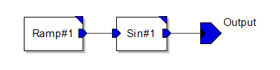
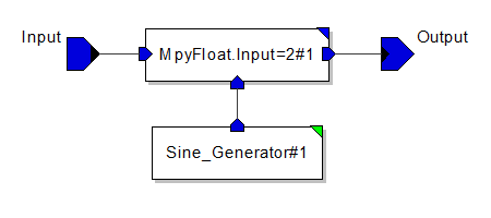
The next step is to connect the model instances of the example models. Start with the creation of connections in the Sine Modulator model.
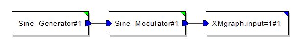
Repeat these steps for the Sine Generator and Sine Modulator System. Your models should now look like this.
|
|
| (a) Sine Generator module | (b) Sine Modulator module |
|
|
| (c) Sine Generator System model | |
Unused ports must be terminated. This is achieved by choosing Terminate from the context menu while the relevant port is selected. In these cases the appropriate BlackHole primitive for output ports and the Const or NULL primitive for input ports for the domain are instantiated.
The next step is to annotate the system with a label.